Contents10 sections
Ask where a subwoofer should go and you get a different fraction from every source. One third of the room length. One fifth. Sixty to eighty percent back. A foot off the wall. In the corner, but not in the corner. And underneath all of it, the advice to put the sub in your chair, crawl around on the floor, and listen.
None of that is wrong, exactly. It is all describing the same physics from the outside. Subwoofer placement is governed by one thing — where the room's standing waves have pressure and where they have none — and once you can calculate that, the fractions stop competing and start agreeing.
This guide works through the physics, then shows how we do the whole job with our own software: modes and placement on the drawing, then measurement and correction on site.
The subwoofer and the sofa follow opposite rules
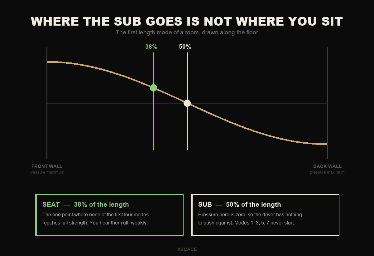
A room mode is a standing wave: a pattern of pressure that sits still between two parallel surfaces. The first length mode has maximum pressure at both end walls and zero exactly halfway between them. The second has maxima at both ends and in the middle. And so on.
Two different objects interact with that pattern in opposite ways.
A listener hears a mode in proportion to the pressure at their ears. Sit at a maximum and that frequency is exaggerated; sit at a zero and it vanishes. So a seat wants a position where no mode is at full strength — which is what the 38% figure is for.
A subwoofer drives a mode in proportion to the pressure where it stands. This is the part that gets lost. A driver sitting exactly on a pressure zero has nothing to push against: it cannot transfer energy into that standing wave, so the mode never gets going in the first place. Placing the sub at a null does not mean the sub is quiet there. It means that particular resonance stays switched off.
Those are genuinely opposite instructions, and conflating them is the single most common error in this subject. The seat rule is covered separately in our piece on the 38% rule — this article is about the source.
Calculate the modes before you move anything
Axial modes — the ones between a single pair of parallel surfaces — are the strongest and the easiest to predict. They take the shortest path and lose the least energy per circuit, so they dominate what you hear.
The frequency of the nth mode along a dimension of length L is n × c ÷ 2L, where c is the speed of sound, 343 m/s at normal room temperature. A 6.00 m dimension gives a first mode at 28.6 Hz, and every whole multiple above it.
| Dimension | Mode 1 | Mode 2 | Mode 3 | Mode 4 |
|---|---|---|---|---|
| Length — 6.40 m | 26.8 | 53.6 | 80.4 | 107.2 |
| Width — 6.00 m | 28.6 | 57.2 | 85.8 | 114.3 |
| Height — 3.00 m | 57.2 | 114.3 | 171.5 | 228.7 |
Read that table across and one thing jumps out. The second width mode and the first height mode both land on 57.2 Hz, and the fourth width mode and the second height mode both land on 114.3 Hz. That is not coincidence — the room is 6.00 m wide and 3.00 m high, an exact 2 : 1, so the two sets of modes stack on top of each other instead of interleaving.
A doubled mode is roughly twice the problem at that frequency and leaves a wider gap on either side. This is the entire argument for proportioned room dimensions, and it is worth knowing before the partitions go up, because afterwards it is unfixable. The room mode calculator does this for a whole room rather than one axis, and flags coincident modes and the widest gap directly.
The arithmetic below is the same calculation, done for every position at once. Enter the room and the seat, and it sums each mode at the listening position for the subwoofer placement you have in mind — then searches a grid of candidates and reports the flattest one it finds.
Work the position out before you crawl
Every room mode to third order is summed at the listening seat — axial, tangential and oblique — for the subwoofer position you enter, and for a grid of 221 candidates. The flattest one wins.
Two things are worth reading off it before moving on. The first is the gap between your position and the best one found: if it is under about half a decibel of variation, the position is already good enough that furniture will matter more than moving the box. The second is the shape of the curve rather than its height — a deep narrow notch is a null you cannot equalise away, while a broad lift is something a calibration pass can genuinely flatten.
Mid-length switches off every odd mode
Put a single subwoofer halfway along the room's length and it sits on the pressure zero of the first, third, fifth and seventh length modes. All of them go quiet. This is a large and free improvement, and it is why the "middle of the side wall" advice keeps resurfacing without explanation.
There is a price, and nobody mentions it. Halfway along the length is a pressure maximum for the second, fourth and sixth modes — it couples to them as strongly as a corner would. You have traded a set of problems for a smaller set of louder ones.
Two subwoofers do better. Place them at 25% and 75% of the length, driven in phase, and the first three length modes cancel: at those two points the odd modes have equal and opposite pressure, and the second mode is zero at both. The fourth mode is reinforced, so the trade is still there, but it has been pushed up to a frequency that is easier to treat and easier to equalise.
| Subwoofer position | Mode 1 | Mode 2 | Mode 3 | Mode 4 |
|---|---|---|---|---|
| Against the end wall | 1.00 | 1.00 | 1.00 | 1.00 |
| 25% of the length | 0.71 | 0.00 | 0.71 | 1.00 |
| 50% — mid-length | 0.00 | 1.00 | 0.00 | 1.00 |
| Two subs at 25% + 75% | 0.00 | 0.00 | 0.00 | 2.00 |
The corner row is there for contrast. A corner is a pressure maximum for every mode along every axis at once, which is exactly why corner placement is loud — it is the most efficient position in the room — and exactly why it is uneven.
The null nobody calculates: the wall behind the speaker
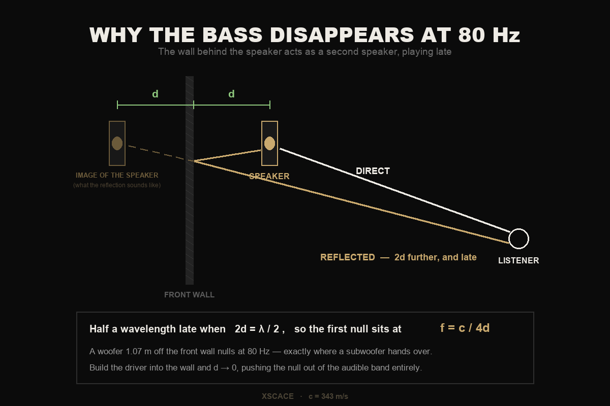
Modes are not the only way bass goes missing. A speaker near a wall is also fighting its own reflection, and this one is easier to calculate than almost anyone assumes.
Sound that leaves the back of the speaker, bounces off the wall behind it and travels on to the listener covers exactly 2d more distance than the direct sound, where d is the speaker's distance from that wall. The reflection behaves like a second, identical speaker standing the same distance behind the wall — its mirror image.
When that extra 2d equals half a wavelength, the reflection arrives perfectly out of step and cancels the direct sound. Setting 2d = λ ÷ 2 and rearranging gives the frequency of the first null: f = c ÷ 4d.
| Distance from wall | First null |
|---|---|
| 0.30 m | 286 Hz |
| 0.50 m | 172 Hz |
| 0.75 m | 114 Hz |
| 1.00 m | 86 Hz |
| 1.07 m | 80 Hz |
| 1.50 m | 57 Hz |
| 2.00 m | 43 Hz |
| 3.00 m | 29 Hz |
The 1.07 m row is the trap. A woofer just over a metre off the front wall puts its deepest cancellation at 80 Hz, which is the crossover frequency almost every system in the world hands over to the subwoofer at. The result is a hole exactly where two devices are supposed to be meeting, and it gets blamed on the crossover, the sub, the amplifier and the cable in roughly that order.
There are only three real answers. Move the speaker much closer to the wall, move it much further out, or take the distance away entirely. The third is the only one that removes the problem instead of relocating it: as d approaches zero the null frequency climbs out of the bass region and out of the audible band altogether. A driver flush in the wall has no gap behind it to reflect off.
That is the honest acoustic case for building speakers into the wall rather than standing them in front of it, and it is one of the reasons we design the way we do. It is a consequence of the geometry, not a feature anyone invented.
Doing this on a drawing, before anyone is on site
None of the arithmetic above needs doing by hand. Our Floorplan Sound Simulation runs in a browser, is free, and takes the floor plan you were already sent. It works best on a laptop or desktop.
You upload the plan, trace each room into a zone by clicking its corners, and set the scale from one known dimension. From that point the room has real geometry, and Analysis › Room Modes lists its axial resonances.
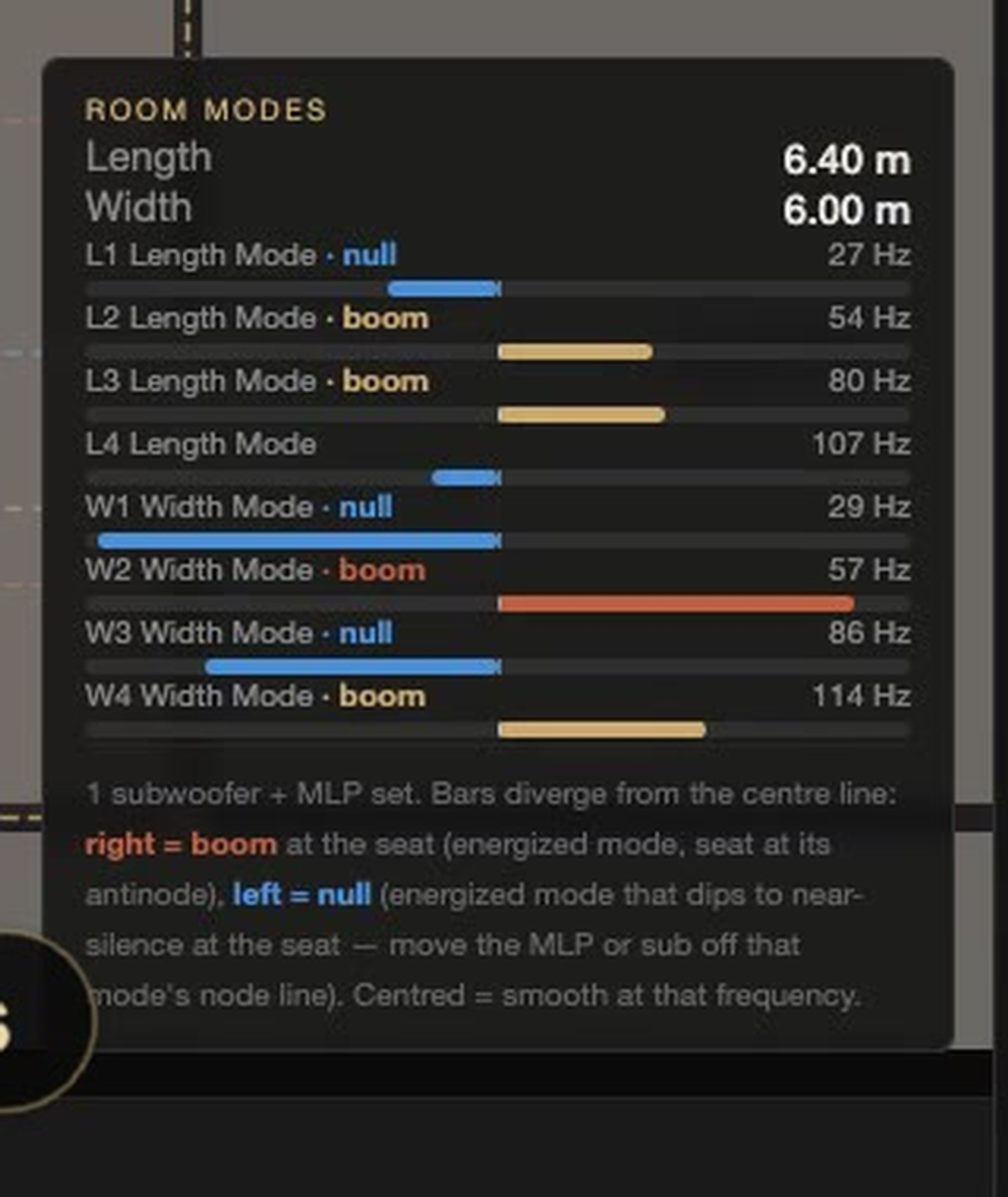
Those are the same figures as the table above, rounded: 27, 54, 80 and 107 Hz along the 6.40 m length, and 29, 57, 86 and 114 Hz across the 6.00 m width. The hand calculation and the simulator agree, which is the point of showing both — you can check the tool rather than trust it.
The column that matters is the one on the right. Each mode is labelled against the subwoofer position and the seat you have set, and the bar diverges from centre to show what that combination does:
- Bar to the right, marked boom — the mode is energised and the seat sits at its antinode. That frequency is exaggerated.
- Bar to the left, marked null — the mode is energised and the seat sits near its node. That frequency drops toward silence.
- Bar centred — nothing to do. The response is smooth at that frequency.
Drag the subwoofer and the labels change live. That is the whole argument of this article turned into something you can operate: you are hunting for centred bars, and every position that produces one is a position where the physics is working for you rather than against you.
With placement settled, Coverage › SPL Map draws predicted level across the zone so you can check the result covers the seats rather than one point.
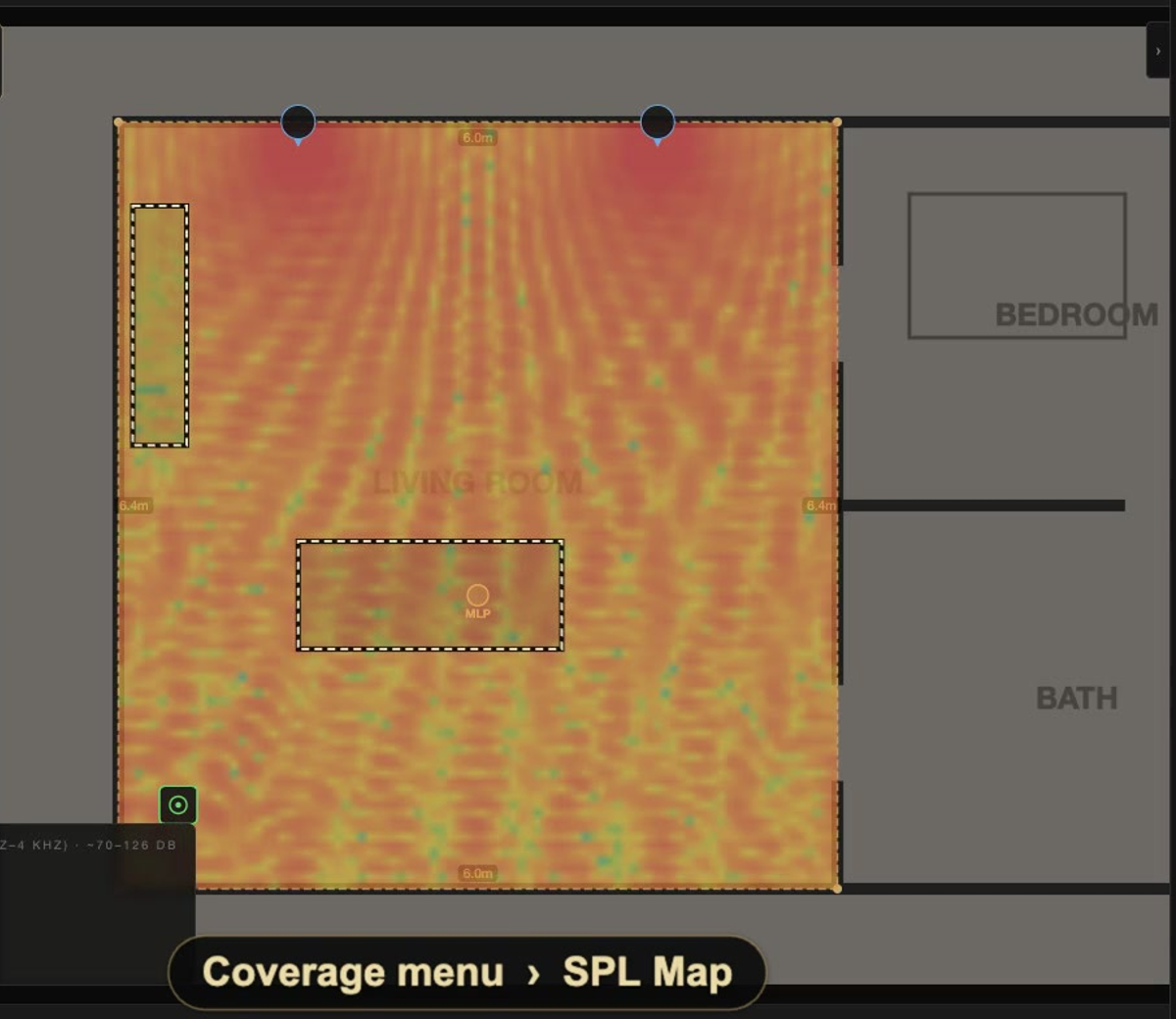
A wall absorptivity control drives how strongly reflections contribute, and switching the zone to Home Cinema adds Dolby reference angles and screen geometry to the same plan. Other manufacturers’ speakers can be modelled alongside ours, which is included with Pro; everything described above is free. There is a full walkthrough in our floorplan sound simulation guide.
Where the subwoofer crawl actually belongs
The crawl — sub in the listening seat, ear at floor level, shuffle around until the bass sounds even — is genuinely good technique, and it works for a real reason. Swap a source and a receiver in a room and the measured response between them is unchanged. So listening from the sub's eventual position, with the sub in your seat, tells you what you will hear from your seat with the sub in that position.
What it cannot do is design anything.
- It optimises one seat. A second row, or a sofa that seats four, is not represented.
- It requires the room to exist, be finished, and have the equipment in it. It is no use at drawing stage, which is when placement is still free to change.
- It tells you where, never why. When the best spot turns out to be somewhere the client will not accept, you have no basis for finding the next best.
- Ears adapt over a few minutes of the same test tone, and the later positions get judged differently from the early ones.
Calculate first, crawl second. The simulator narrows a room to two or three candidate positions before anyone is on site; the crawl, or a proper measurement pass, picks between them.
Proving it on site, in the order that works
Once the sub is physically in the room, the job stops being prediction and becomes measurement. XSCACE Studio is our desktop application for Mac and Windows; it programs the Xylem DSP amplifier series and carries an eleven-instrument measurement toolkit. Every instrument also runs standalone with no amplifier connected, so it will measure a third-party system just as readily.
Sub Align is the instrument to reach for first, because subwoofer integration is the step most often got wrong.
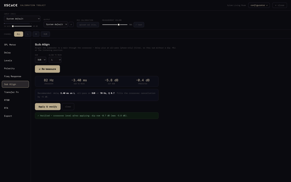
It finds the actual acoustic crossover point — 82 Hz in the session shown — and checks whether the sub and the mains are summing there or fighting. This is where a front-wall null of the kind calculated earlier shows up as a real measurement rather than a suspicion: if the mains are cancelling at 80 Hz, the handover is happening straight into a hole, and no amount of level trim will fix it.
Next, delay, levels and polarity. One sweep per channel measures true acoustic arrival at the listening position and returns a table rather than a graph to squint at.
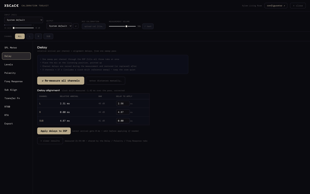
Two details in that table matter more than they look. Each channel carries its own signal-to-noise figure, so a measurement taken in a room that was not quiet enough is visible rather than silently wrong. And clock drift between the audio interface and the DSP is measured across the pass and corrected, rather than being baked into the alignment.
Calibrate — and only then equalise
Two room measurements decide whether the system will sound clear once furniture, glass and plasterboard are involved, and neither is about the speakers.
RT60 is how long the room keeps talking after the sound stops — reverberation time, measured to ISO 3382, with a spectral decay waterfall showing which frequencies hang on longest. Domestic listening wants roughly 0.3 to 0.5 seconds.
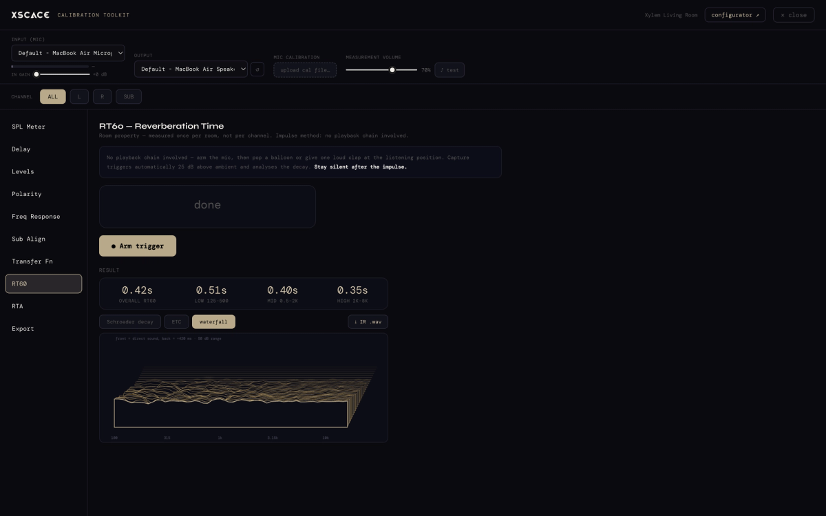
The other is the noise floor. The real-time analyser rates background noise on the NC scale from NC-15 to NC-65, and it is the quantity that silently sets the ceiling on everything else: a room at NC-40 has buried the quietest 25 dB of the recording before a speaker has played a note.
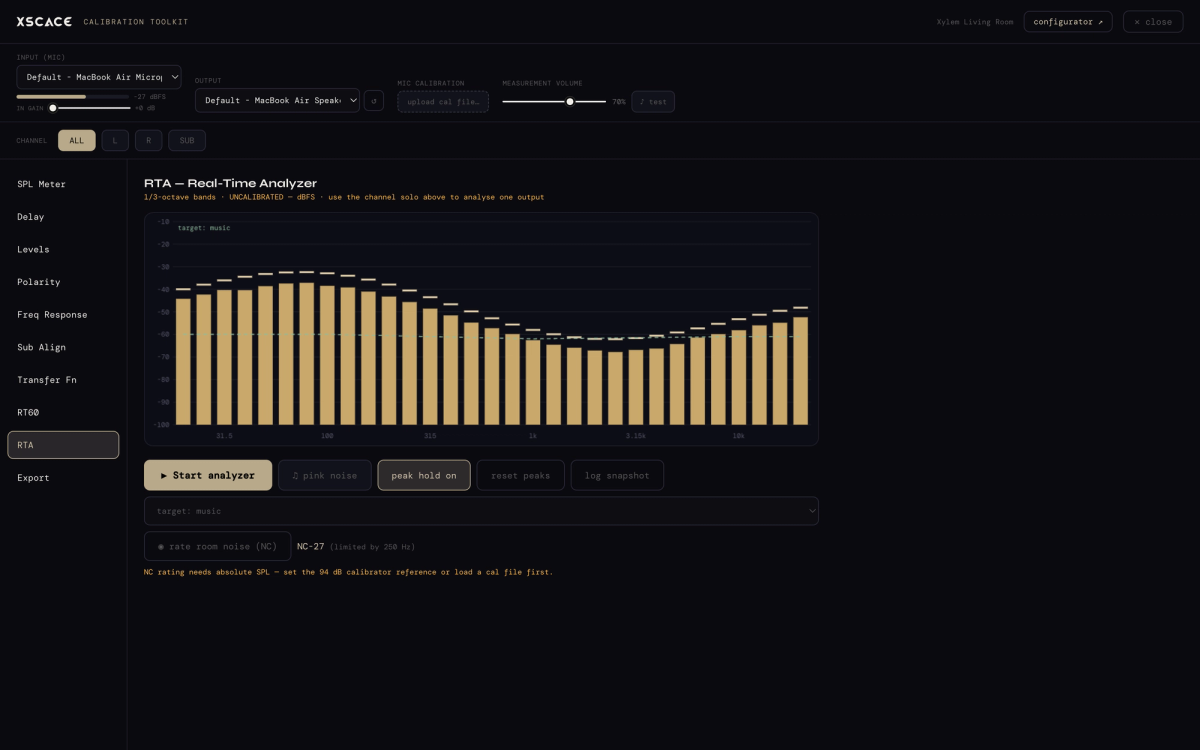
Only now does equalisation make sense, and one asymmetry decides how it is used.
A peak can be pulled down. Cutting gain at a resonant frequency is exactly what parametric equalisation is for, and done narrowly it is close to invisible. Each output channel in Studio carries six bands, each settable as a peaking filter or a shelf.
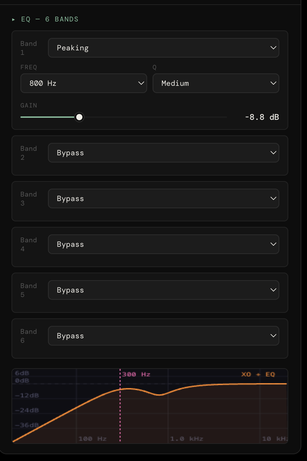
A null cannot be filled. At a cancellation the room is subtracting the energy as fast as the speaker supplies it, so adding gain produces excursion, distortion and heat in the amplifier — and no more output at the seat. This is why every experienced calibrator cuts rather than boosts below 500 Hz, and why placement is settled before correction is touched.
X-Sense Auto EQ will run the sweep and generate corrective curves automatically across a multi-zone system, and Auto Delay will time-align up to 27 ms without hand-entered distances. All eleven instruments are covered in our guide to audio calibration software.
Closing the loop: the measurement goes back on the drawing
The last step is the one that turns a prediction into a record. Each zone in the Floorplan Sound Simulation has fields for measured RT60 and measured ambient noise in NC. Type in what Studio actually recorded and those figures are stamped into the exported report alongside the predicted coverage maps.
What was a design document becomes a verified as-built one. The client receives a report that says what the room was expected to do and what it measured, on the same page — and if a complaint arrives eighteen months later, there is a baseline to compare against rather than a memory of a good afternoon.
The BOQ and client proposal export from the same project, so quantities, coverage and measured performance stay attached to one file. That is the same reasoning behind how we run an installation end to end.
A working order
- Trace the plan and set the scale in the Floorplan Sound Simulation. Read Analysis › Room Modes and note any frequency that appears on more than one axis.
- Place the seats first, away from pressure maxima — around 38% of the room length is the usual starting point, and never hard against the back wall.
- Move the subwoofer until the modes you care about show centred bars rather than boom or null. Mid-length for a single sub; 25% and 75% for a pair.
- Check each main speaker's distance to the wall behind it against f = c ÷ 4d, and make sure that null is not sitting on your crossover frequency.
- On site, run Sub Align first, then delay, levels and polarity — one sweep per channel.
- Measure RT60 and the NC noise floor before touching any filter.
- Equalise last, cutting peaks and never filling nulls.
- Enter the measured RT60 and NC back into the zone, and export the report.
Steps one to four cost nothing and happen on a drawing. Steps five to eight need the room. The gap between them is where most of the performance is won or lost, which is why placement is a design deliverable here rather than something discovered on commissioning day.