Contents4 sections
The acoustic performance of any in-ceiling or in-wall speaker is determined as much by installation quality as by the hardware itself. A speaker installed without a backbox into an open ceiling plenum will underperform a less expensive unit installed correctly — with an acoustic backbox, proper cable gauge, and correct amplifier matching. This in-ceiling speaker installation guide covers the entire process from rough-in through to final commissioning, written for both the AV integrator specifying on technical merit and the homeowner who wants to understand exactly what a correct installation requires.
At XSCACE, we engineered every speaker in our range — from the 12mm Bonsai slim-array to the Acacia 10, which extends to 35Hz — to perform to specification only when the installation meets defined mechanical and electrical conditions. Shortcuts at the installation stage create acoustic defects that no amount of DSP correction can fully remedy. What follows is the process we recommend to every integrator who specifies our products.
Rough-In Stage: What to Do Before Walls and Ceilings Close
Rough-in is the most consequential stage of any architectural audio installation. Decisions made here — cable routing, speaker positioning, backbox placement — are either correct and invisible, or wrong and permanently expensive to correct. Once plasterboard is up and finished surfaces are applied, errors cost ten times what they would have cost to prevent.
- Mark speaker positions on structural drawings — confirm no joists, pipes, or HVAC ducts occupy the planned locations before cutting begins
- Run speaker cable home-run from each speaker position to the amplifier location — do not daisy-chain; home-run wiring eliminates shared-load impedance errors and simplifies future diagnostics
- Cable gauge: 16AWG minimum for runs up to 20m; 14AWG for runs 20–50m; 12AWG for runs over 50m — undersized cable adds series resistance and reduces damping factor at the speaker
- Install conduit sleeves at every speaker position even where cable is already run — this enables future cable upgrades or speaker replacements without opening finished ceilings
- Mount acoustic backboxes at all speaker positions before plasterboard goes up — mark backbox centres precisely, as a 10mm positioning error becomes visible as an uneven gap around the grille trim
- Label all cables at the amplifier end with room identifier and L/R channel designation before the ceiling closes — unlabelled cable looms are one of the most common causes of commissioning delays
Backboxes: Why They Are Non-Negotiable in a Quality Installation
Without a backbox, the ceiling plenum becomes the speaker's enclosure. Plenum volume is unpredictable — it changes between rooms, it is often partially filled with insulation or crossed by HVAC ductwork, and it is acoustically shared across multiple ceiling cavities. A speaker whose rear wave couples into an undefined plenum volume will produce bass response that bears no relation to its specification sheet. The manufacturer measured that speaker in a defined test enclosure. Your ceiling is not that enclosure.
Acoustic backboxes solve four distinct problems simultaneously: they provide a consistent enclosed volume for predictable bass response; they provide acoustic isolation between rooms so that sound from one space does not transmit structurally into adjacent rooms through a shared plenum; they deliver fire rating compliance when specified to local building code requirements; and they protect the speaker chassis from insulation debris and condensation that would otherwise settle on the cone over time.
XSCACE recommends ABS or steel acoustic backboxes sized to each speaker model's recommended internal volume. At every cable entry point into the backbox, apply acoustic sealant to prevent flanking transmission and maintain the fire rating of the assembly. A backbox with unsealed cable penetrations provides partial acoustic isolation at best.
Installation Day: Cutting, Mounting, and Wiring
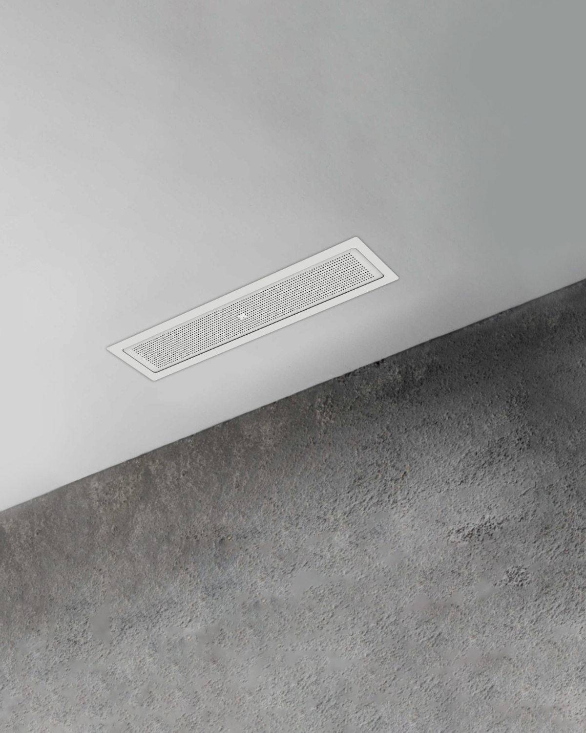
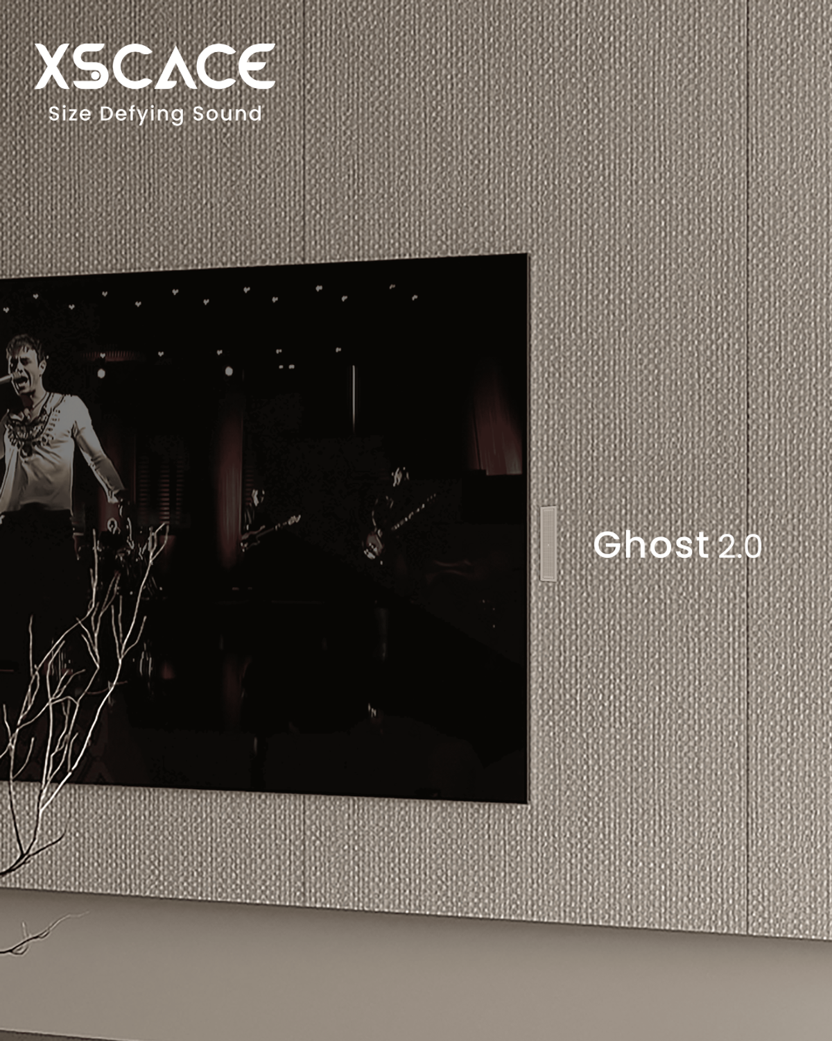
Use the supplied cutting template for each speaker model. The aperture size is not approximate — too large produces a visible gap between the ceiling surface and the grille trim ring; too small causes the chassis to bind against the ceiling material, which loads the cabinet and distorts bass response. For standard plasterboard ceilings, a fine-tooth jab saw or oscillating tool works cleanly. For plaster ceilings, use a diamond-tipped hole saw at slow cutting speed to avoid cracking the substrate. Not every model takes a round hole: the Ghost 2.0 cuts a 169 × 54 mm rectangular aperture and mounts on a bracket fitted before the ceiling closes, with the speaker attaching magnetically afterwards — so the template and the sequence both differ from a dog-leg model.
When connecting terminals, strip exactly 15mm of insulation — no more, as exposed conductor beyond the terminal creates a short risk in a metal backbox. Twist the conductor strands firmly before insertion. Confirm positive (+) to positive and negative (−) to negative on every channel. A single polarity reversal on one speaker inverts its phase relative to the rest of the system: the two speakers will partially cancel each other in the frequency range where their outputs overlap, collapsing stereo imaging and reducing bass output. Polarity errors are silent at the terminal — they only become audible during commissioning, after the ceiling is finished.
When mounting, tighten the dog-leg clamps evenly and progressively — alternate sides rather than fully tightening one clamp before moving to the next. Over-tightening cracks plasterboard around the aperture; under-tightening allows the speaker to rotate over time as ceiling vibration loosens the assembly. XSCACE in-ceiling speakers use magnetic grille retention — there are no visible screws, and the grille seats flush with the ceiling surface without tools.
Commissioning: System Level Checks Before Sign-Off
Commissioning is the verification stage — it confirms that every installation decision made during rough-in and installation day produced the intended electrical and acoustic result. Do not skip commissioning on the grounds that everything looks correct. Polarity errors, impedance mismatches, and level imbalances are not visible. They must be measured.
- Impedance check: use an impedance bridge or AV receiver test tone to confirm each channel's impedance matches specification — a significant deviation indicates a wiring fault, damaged driver, or incorrect parallel load
- Polarity check: play a mono reference track with a centred phantom image — a correctly wired stereo pair produces a stable, focused phantom centre; a polarity reversal on one channel produces a diffuse or spatially inconsistent image
- Level matching: use a calibrated SPL meter at the primary listening position and match all zones to within ±1dB — level imbalance between channels is perceived as a shifted stereo image and uneven room coverage
- Bass management: confirm subwoofer crossover point and output level — for systems using the XSCACE Acacia 6 (45Hz–300Hz, 84dB sensitivity), set the satellite high-pass filter at 80Hz to relieve the in-ceiling drivers of low-frequency work they are not sized to reproduce
- DSP commissioning: if the system uses the XSCACE Xylem amplifier series, run the PsySculpt™ room calibration routine to apply measured room correction across all active channels
- Handover documentation: provide the client with a system diagram showing speaker positions, amplifier channel assignments, zone identifiers, and cable labels — this document halves the time required for any future service call
A correctly installed XSCACE system requires no acoustic treatment panels, no specialist room correction consultant, and no ongoing manual adjustment. The Acacia 10, with its 35Hz–300Hz bandwidth and 88dB sensitivity, will reproduce the full acoustic content of any source material when installed into a correctly specified backbox and driven by a properly matched amplifier. The investment is in the installation quality on day one — not in remediation afterward.