Contents6 sections
To calculate passive crossover components, divide the Butterworth coefficient for that order by 2πfR for a capacitor in farads, or multiply it by R/2πf for an inductor in henries, where f is the crossover frequency and R the driver impedance. A second-order 8 ohm crossover at 2.5 kHz needs a 5.63 µF capacitor and a 0.72 mH inductor. The calculator below returns every value for first, second and third order high-pass and low-pass filters.
Capacitor and inductor values
Butterworth alignment into a nominal resistive load. A high-pass protects a tweeter by removing everything below the corner; a low-pass keeps a woofer from reaching up past it. Each order adds 6 dB per octave and one more component.
12 dB/octave Butterworth, R = 8 Ω, f = 2500 Hz
| Order | Slope | High-pass | Low-pass |
|---|---|---|---|
| 1st | 6 dB/oct | C = 1 / 2πfR | L = R / 2πf |
| 2nd | 12 dB/oct | C = 0.7071 / 2πfR, L = 1.4142R / 2πf | L = 1.4142R / 2πf, C = 0.7071 / 2πfR |
| 3rd | 18 dB/oct | C = 0.6667 / 2πfR, L = 0.75R / 2πf, C = 2 / 2πfR | L = 1.5R / 2πf, C = 1.3333 / 2πfR, L = 0.5R / 2πf |
| Order | High-pass | Low-pass |
|---|---|---|
| 1st | C 7.96 µF | L 0.51 mH |
| 2nd | C 5.63 µF, L 0.72 mH | L 0.72 mH, C 5.63 µF |
| 3rd | C 5.31 µF, L 0.38 mH, C 15.92 µF | L 0.76 mH, C 10.61 µF, L 0.25 mH |
Should you use a capacitor or an inductor?
The component follows from the job, not the other way round:
- A capacitor passes high frequencies and blocks low ones. In series with a tweeter it forms a high-pass filter — the standard way to keep bass out of a driver that cannot survive it.
- An inductor passes low frequencies and blocks high ones. In series with a woofer it forms a low-pass filter, stopping the woofer reaching up into the tweeter’s range.
A first-order filter is a single component: one capacitor for a high-pass, one inductor for a low-pass. Higher orders alternate the two, adding a shunt component across the driver for each additional order.
What does filter order change?
Each order adds 6 dB per octave of slope and one more component:
- First order, 6 dB/octave — one part, minimum phase shift (90°), and the gentlest transition. It also leaves the tweeter exposed: an octave below the crossover the filter is only attenuating by 6 dB, which is rarely enough protection.
- Second order, 12 dB/octave — two parts, 180° of phase shift, and the most common choice in passive design. The phase shift usually means reversing one driver’s polarity to keep the crossover region filled in.
- Third order, 18 dB/octave — three parts, 270° of phase shift, and tight driver protection. The steep slope narrows the band where both drivers contribute, which reduces lobing but makes the design less forgiving of driver offset.
The alignment here is Butterworth, which is maximally flat in the passband and sums to a 3 dB bump through the crossover region when both halves are in phase. It is the standard textbook starting point rather than the final answer.
Why do calculated crossover values not measure right?
Every passive crossover calculator treats the driver as a resistor. Drivers are not resistors. Impedance rises with frequency because of voice-coil inductance, and it peaks sharply at the driver’s free-air resonance — an 8 ohm woofer can present 30 ohms or more at resonance and climb well above 8 ohms in the top of its range.
Because the filter’s corner frequency depends on the load it sees, a crossover calculated against a nominal 8 ohms will put its real acoustic corner somewhere else entirely. The usual fix is a Zobel network — a resistor and capacitor in parallel with the driver that flattens the rising impedance so the filter sees something closer to the resistance it was designed for.
Two more things the arithmetic cannot see. The acoustic slope is the electrical slope plus the driver’s own natural roll-off, so a driver already falling at 6 dB/octave turns a second-order electrical filter into a third-order acoustic one. And odd-order filters leave the two outputs 90° apart, which is why one driver is so often wired in reverse polarity.
When should you use an active crossover instead?
Passive crossovers work after the amplifier, which means they dissipate real power as heat, they interact with the driver’s impedance curve, and they cannot be changed without unsoldering parts. An active crossover ahead of the amplifier has none of those constraints: the filter sees a fixed input impedance, the slope and frequency are set in software, and each driver gets its own amplifier channel.
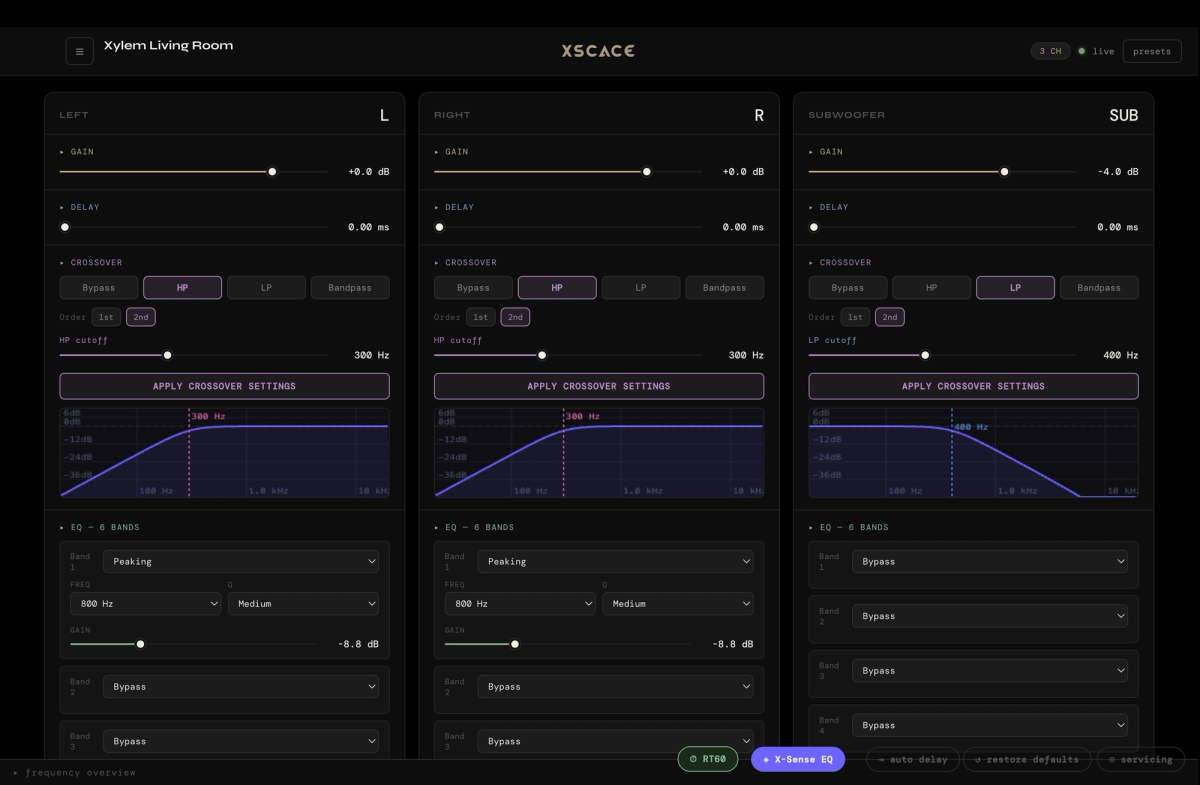
That is what the DSP in an XSCACE amplifier does — crossover, time alignment and equalisation set per channel and changed without touching the speaker.
A worked example: a 6 ohm tweeter at 3 kHz
A 6 ohm dome tweeter crossed at 3 kHz, second order, protecting it from everything below.
- C1, in series with the tweeter: 0.7071 / (2π × 3000 × 6) = 6.25 µF.
- L1, in parallel across the tweeter: 1.4142 × 6 / (2π × 3000) = 0.45 mH.
Order those two parts and the electrical filter is correct. The acoustic result usually is not, for a reason that has nothing to do with the arithmetic: at 3 kHz that tweeter probably measures nearer 7 or 8 ohms than 6, because voice-coil inductance has already started to lift the impedance. The filter therefore corners lower than 3 kHz and rolls off more gently than 12 dB per octave.
The honest sequence is calculate, build, measure, adjust. Use these values as the starting point, flatten the impedance with a Zobel network if the rise is significant, then measure the acoustic response and move the values to suit what the drivers actually do in the cabinet. A crossover that was never measured is a guess with components soldered to it.
How do you build a 2-way or 3-way crossover?
The calculator returns one filter at a time, because that is what a crossover is made of. A complete network is two or three of them sharing a frequency:
- A 2-way crossover is one low-pass on the woofer and one high-pass on the tweeter, both at the same frequency and the same order. Run the calculator twice — once for each — and you have the full parts list.
- A 3-way crossover adds a midrange band-pass between them, which is a high-pass at the lower crossover point and a low-pass at the upper one, in series on the same driver. So three runs of the calculator: low-pass at f₁ for the woofer, high-pass at f₁ plus low-pass at f₂ for the midrange, high-pass at f₂ for the tweeter.
Two cautions specific to multi-way networks. Drivers rarely share an impedance — a 4 ohm woofer with an 8 ohm tweeter needs each filter calculated against its own figure, not a single nominal value for the speaker. And a midrange band-pass with the two corners closer than about three octaves starts to interact, dropping its passband level below what either filter predicts on its own.