Contents5 sections
The most successful architectural audio projects share one characteristic: the audio system was specified at the design stage, not retrofitted after construction. Knowing how to specify architectural speakers correctly — positions, cabling routes, backboxes, and amplifier locations resolved before a single wall closes — is the difference between an invisible system that performs without compromise and an afterthought that never quite sounds right. This guide is written for interior designers, architects, and AV integrators who want to get the specification right from day one.
At XSCACE, we work with specifiers across Canada and internationally on projects ranging from single-room installs to whole-home audio across multi-thousand-square-foot residences. The technical lessons are consistent: specification errors made at the design stage are expensive to fix, and most of them are entirely avoidable.
The Design Stage Checklist: What to Lock Down Before Walls Close
Eight items must be resolved and documented in the architectural drawing set before rough-in begins. Miss any one of them and you are creating a problem that will be solved with compromise rather than engineering.
- Speaker positions on the reflected ceiling plan — mark the centre of each speaker, confirm stud and joist clearance for the backbox depth required.
- Cable routes — specify home-run cable runs from each speaker position to a single amplifier location. Daisy-chain wiring introduces impedance variability and should never appear in a luxury specification.
- Amplifier and rack room — allocate a minimum of 0.6m² for a residential whole-home audio rack. Ventilation, power, and network access must all be resolved in this space.
- Backbox specification — always specify backboxes for isolated ceiling cavities. An open-back installation lets bass energy propagate through the floor cavity, producing bass smear and room-to-room cross-talk that no amount of DSP correction can fully resolve.
- Conduit sleeves for future cabling — even where wireless streaming is planned, sleeve all speaker positions. Technology changes; conduit costs almost nothing at rough-in and avoids costly remediation later.
- Power for amplifiers — specify dedicated 20A circuits for audio equipment, isolated from HVAC and lighting circuits. Shared circuits introduce noise floor problems that appear unpredictably after occupancy.
- Ceiling profile — note ceiling height, material, and any acoustic treatment planned. These factors affect backbox depth requirements and driver selection across the range.
- Commissioning access — specify access panels at all amplifier locations. Audio systems require periodic calibration and hardware servicing; locking the rack behind finished millwork is a maintenance liability.
Choosing the Right Speaker for the Space
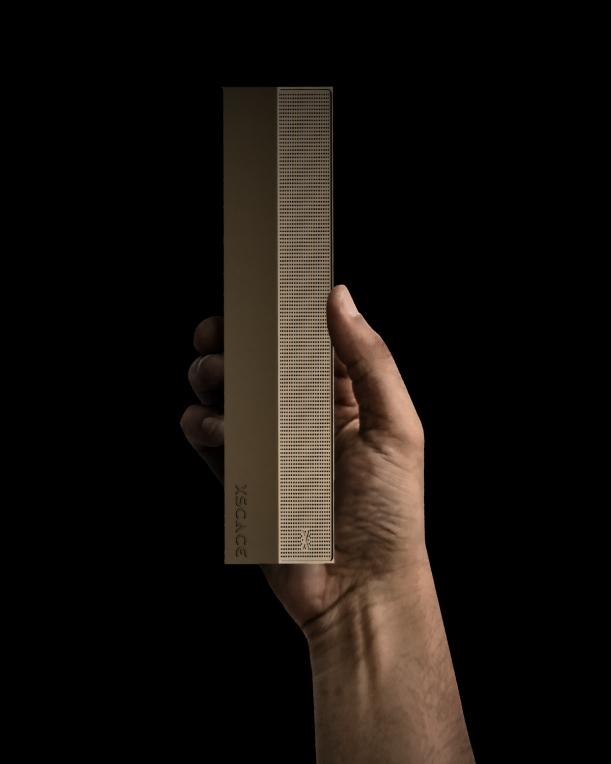
Driver size is determined by room volume, not by personal preference. For rooms under 40sqm, a 6.5" in-ceiling or in-wall driver delivers sufficient output without creating near-field listening problems. Above 40sqm, specify 8" drivers or use multiple 6.5" drivers per zone — the physics of low-frequency coverage requires it. A single 6.5" driver attempting to cover a 60sqm open-plan kitchen and living area will be driven hard to meet output expectations, and thermal compression will degrade dynamic range during sustained listening levels.
Sensitivity matching across zones is a specification requirement that is frequently overlooked. If Zone A runs 88dB sensitivity speakers and Zone B runs 84dB speakers from the same amplifier, the amplifier must be set to two different output levels to achieve consistent perceived loudness. In multi-zone whole-home systems, this creates a calibration dependency that adds commissioning complexity and limits control system automation. We specify matched-sensitivity speakers across all zones in any system where consistent whole-home volume behaviour is a requirement.
Aesthetic specification matters as much as acoustic specification for interior designers. XSCACE provides RAL colour matching for custom grille finishes across the in-ceiling, in-wall, slim-array, and outdoor ranges. Trim ring profiles can be specified to match reveal depth, and grille colour is confirmed at the design stage so there are no surprises during installation.
Amplifier and DSP Specification
The rule for luxury architectural audio is straightforward: one amplifier channel per speaker. Zone amplifiers driving multiple speakers in parallel change the impedance load presented to the amplifier, reduce the amplifier's control over each individual driver, and make DSP correction per-speaker impossible. In a high-performance installation, parallel wiring is never acceptable. This is a specification constraint, not a cost option.
DSP capability is not optional in any installation where room acoustics are uncertain — which is every installation. Room boundary effects, ceiling height, furnishing density, and reflective surface area all alter the frequency response at the listening position. The XSCACE Xylem DSP amplifier series provides per-channel DSP, PsySculpt™ room correction, and integrated streaming. Per-channel DSP means the correction is applied to each individual speaker after the room has been measured — the only technically rigorous approach to consistent performance across a multi-room installation.
Control system integration must be confirmed at the specification stage. Confirm that the specified amplifier supports the communication protocol required by the control system — whether Control4, Crestron, Lutron, or a proprietary platform. Retrofitting control integration after installation is both expensive and technically compromised.
Common Specification Errors and How to Avoid Them
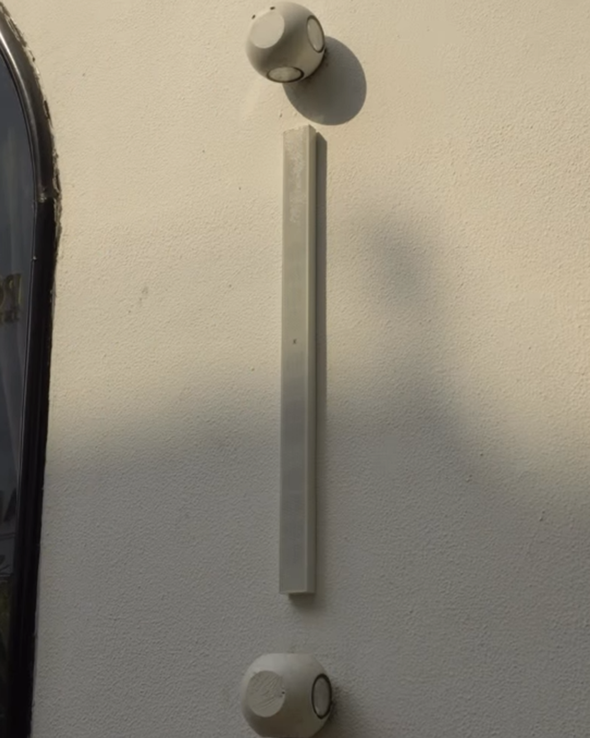
The following errors appear repeatedly across installation projects. Each one is preventable at the specification stage and costly to correct after construction is complete.
- Under-specifying cable gauge: use minimum 16AWG for all speaker cable runs. For runs exceeding 20 metres, specify 14AWG. Resistance losses on undersized cable reduce damping factor and cause measurable high-frequency rolloff — both audible at reference listening levels.
- Omitting backboxes: open-back ceiling installation allows bass energy to propagate freely through the ceiling cavity. The result is unpredictable low-frequency response, room-to-room cross-talk, and in multi-storey installations, audible bleed between floors.
- Daisy-chaining zones: series or parallel wiring changes the impedance presented to the amplifier and reduces the amplifier's ability to control each individual driver. Never acceptable in a performance installation.
- Incorrect impedance matching: confirm that the amplifier's stable impedance rating matches the speaker impedance. A 4Ω-rated amplifier driving an 8Ω speaker is inefficient; an 8Ω-rated amplifier driven into a 4Ω load will trigger protection circuits or fail prematurely.
- No commissioning clause: the AV contractor's scope of work must include audio commissioning and final calibration as a line item. Systems delivered without calibration are never performing to specification, regardless of how well the hardware was installed.
Working with the XSCACE Specification Team
XSCACE's specification team is available to assist on projects from early design stage through to commissioning. We provide room-by-room driver selection, amplifier channel count calculations, cable schedule templates, and backbox specifications in a format suitable for inclusion in the architectural drawing set. Contact us at support@xscace.com or through our distributors page. Specification support is provided at no charge for qualified residential and commercial projects. The acoustic performance of your installation begins with the specification document — get it right, and the rest follows.